
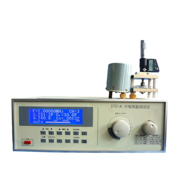

STD-A Permittivity Tester


- Description
- Inquiry
Description
STD-A Permittivity Tester
Introduction
Dielectric loss and dielectric constant is an important physical property of all kinds of electric porcelain, device porcelain, capacitors and other ceramics, as well as composite materials, etc. By measuring the dielectric loss Angle tangent tanδ and dielectric constant (ε), we can further understand the various factors affecting dielectric loss and dielectric constant, to provide a basis for improving the performance of materials; The basic principle of the instrument is the use of high frequency resonance method, and provides a universal, multi-purpose, multi-range impedance test. It uses a single chip computer as the control of the instrument, Q value range automatic conversion, numerical display and other new technologies, improve the tuning loop, so that the residual inductance of the tuning test loop is reduced to the minimum, and retains the automatic amplitude stabilization technology in the original Q table, making the new instrument more convenient to use and more accurate measurement value. The instrument can measure the Q value of the high-frequency inductor or resonant loop, the inductance and distributed capacitance of the inductor, the capacitance and loss Angle tangent value of the capacitor, the high-frequency dielectric loss of electrical materials, the effective parallel and series resistance of the high-frequency loop, the characteristic impedance of the transmission line under the condition of a higher test frequency. The instrument is used in research institutions, schools, factories and other units to study the properties of inorganic non-metallic new materials. The instrument complies with the standard: GB/T5594.4-1985.
Technical specifications of the instrument
1. Q value measurement
a.Q value measurement range: 2 ~ 1023;
b.Q value range: 30, 100, 300, 1000, automatic shift or manual shift;
c. Nominal error
Frequency range 10kHz to 10MHz
Inherent error ≤ 5% ± 2% of full degree value
Operating error ≤ 7% ± 2% of full degree value
Frequency range 10MHz to 70MHz
Inherent error ≤ 6% ± 2% of the full degree
Operating error ≤ 8% ± 2% of the full degree
2. Inductance measurement range: 1nH ~ 8.4H
3. Capacitance measurement:
Direct measuring range 1 ~ 520p
Main capacitance adjustment range 30 ~ 550pF
accuracy 100pF or less ±1pF; ±1% above 100pF
Note: For capacitance measurements larger than the direct measurement range, see Usage method.
4. Signal source frequency coverage:
Frequency range 10kHz to 70MHz
CH1 10 ~ 99.9999kHz
CH2 100 ~ 999.999kHz
CH3 1 to 9.99999MHz
CH4 10 to 70MHz
Frequency indication error 3×10⁻⁵±1 word
5. Q Qualified indicator Preset function: Preset range: 5 to 1000
6. Normal working conditions of Table Q
a. Ambient temperature: 0℃ ~ +40℃;
b. Relative humidity: < 80%;
c. Power supply: 220V±22V, 50Hz±2.5Hz.
7. Power consumption: about 25W;


