




KDZD Insulation Withstand Voltage Tester


- Opis
- Povpraševanje
Opis
Insulation Withstand Voltage Tester
Predstavitev izdelka
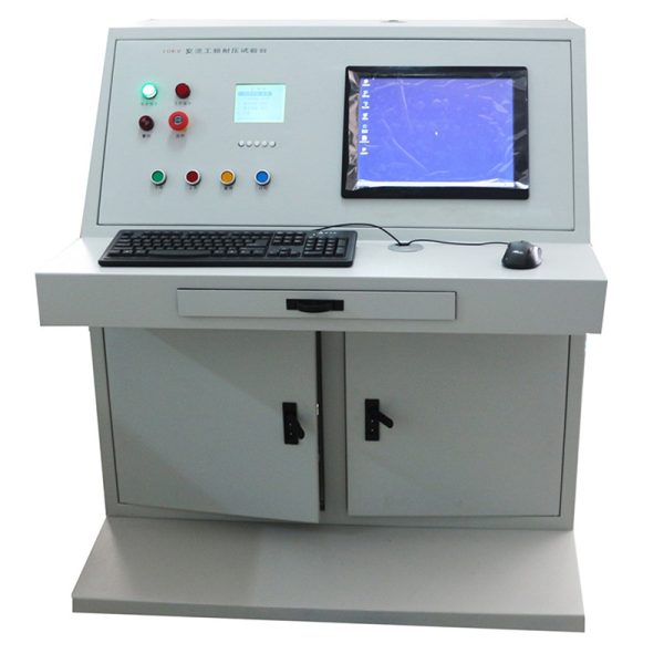
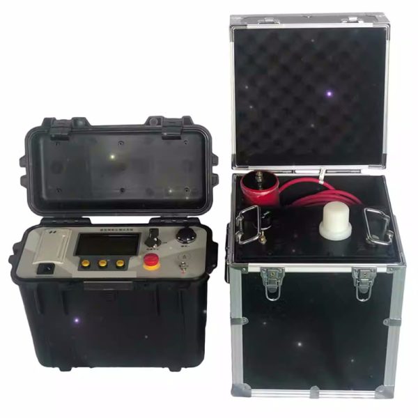
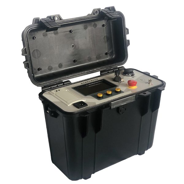
This product combines modern digital frequency conversion technology, the use of microcomputer control, boost, buck, measurement, protection automation. Because of electronization, so small volume and light weight, large screen LCD display, clear and intuitive, and can display output waveform, print test report. The design indicators conform to the “general technical conditions for special test instruments for power equipment, del 4: General technical conditions for ultra-low frequency high voltage generators” power industry standards, enostaven za uporabo. Now both at home and abroad use mechanical methods for modulation and demodulation to generate ultra-low frequency signals, so there is a sine wave waveform is not standard, the measurement error is large, the high voltage part has spark discharge, the equipment is bulky, and the two, four quadrants of the sine wave also need high power high voltage resistor discharge shaping, so the overall power consumption of the equipment is large. This product has no such shortcomings, in addition, there are the following characteristics need special explanation:
1. Trenutno, voltage and waveform data are directly sampled from the high voltage side, so the data are accurate.
2. With over-voltage protection function, ko izhod preseže nastavljeno mejno vrednost napetosti, instrument bo zaustavil zaščito, the operation time is less than 20ms.
3. With over-current protection function: designed for high and low voltage dual protection, high voltage side can be precise shutdown protection according to the set value; When the current of the low voltage side exceeds the rated current, Zaščita pred zaustavitvijo bo izvedena, in čas delovanja je krajši od 20 ms.
4. The high voltage output protection resistor is designed in the boost body, so there is no need for another protection resistance outside.
5. Because of the use of high and low voltage closed-loop negative feedback control circuit, the output has no capacity rise effect.
Insulation Withstand Voltage Tester
1. Nazivna izhodna napetost:
|
Rated voltage |
Carrying capacity |
Napajanje |
Product structure, teža |
|
30kV |
0.1Hz,≤1.1µF |
10A |
Controller: 4㎏ |
|
0.05Hz,≤2.2µF |
|||
|
0.02Hz,≤5.5µF |
|||
|
50kV |
0.1Hz,≤1.1µF |
10A |
Controller: 4㎏ |
|
0.05Hz,≤2.2µF |
|||
|
0.02Hz,≤5.5µF |
|||
|
80kV |
0.1Hz,≤1.1µF |
15A |
Controller: 4㎏ |
2. Izhodna frekvenca: 0.1Hz, 0.05Hz, 0.02Hz
3. Load capacity: 0.1Hz, maximum 1.1µF; 0.05Hz, maximum 2.2µF; 0.02Hz with a maximum of 5.5µF 4. Natančnost meritev: 3%
5. Voltage positive, negativna vršna napaka: ≤ 3%
6. Voltage waveform distortion: ≤ 5%
7. Pogoji uporabe: indoor, outdoor; Temperatura: -10℃ ~ +40 ℃; Vlažnost: ≤ 85 % RH
Insulation Withstand Voltage Tester
9. Municipal power supply: frekvenca 50Hz, napetost 220V±5%. If the use of portable generator power supply, generator requirements: frekvenca 50Hz, napetost 220V±5%, power should be greater than 3KW, and in the output of the generator in parallel a power of not less than 800W resistive load (such as electric furnace), in order to stabilize the speed of the generator. Otherwise the instrument will not work properly.
Products with appropriate specifications were selected according to the subject’s orientation. When used, the capacity of the test shall not exceed the rated capacity of the instrument. If the sample capacitance is too small, it will affect the output waveform. If it is less than 0.05µF, the instrument will not output normally. V tem primeru, the capacitor of 0.05µF (provided by the company) can be connected in parallel to assist the output. The following is the electrical capacity of some devices for user reference.
Insulation Withstand Voltage Tester
Single-phase to ground electric capacity of different generators
|
|
Pyroelectric power |
Water and electricity |
|||||
|
Generator capacity |
200 |
300 |
600 |
85 |
125-150 |
300 |
400 |
|
Single-phase capacitance to ground (µF) |
0.2-0.25 |
0.18-0.26 |
0.31-0.34 |
0.69 |
1.8-1.9 |
1.7-2.5 |
2.0-2.5 |
Capacitance of Cross-linked Polyethylene Insulated Single-core Power Cable (µF/km)
|
Cross section Capacitor mm2 µF/Km Voltage kV
|
16 |
25 |
35 |
50 |
70 |
95 |
120 |
150 |
185 |
240 |
270 |
|
10 |
0.15 |
0.17 |
0.18 |
0.19 |
0.21 |
0.24 |
0.26 |
0.28 |
0.32 |
0.38 |
– |
|
35 |
– |
– |
– |
0.11 |
0.12 |
0.13 |
0.14 |
0.15 |
0.16 |
0.17 |
0.19 |