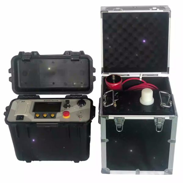

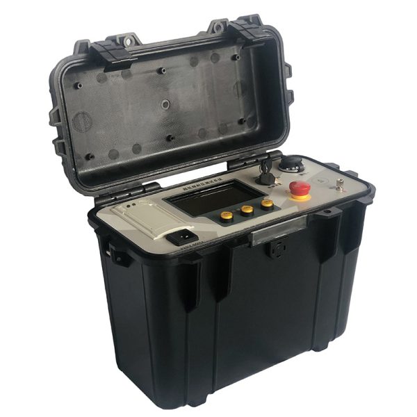




KDZD Insulation Withstand Voltage Tester


- Descripción
- Consulta
Descripción
Insulation Withstand Voltage Tester
Introducción del producto
This product combines modern digital frequency conversion technology, el uso del control por microcomputadora, aumentar, dólar, medición, automatización de protección. debido a la electronización, volumen tan pequeño y peso ligero, pantalla LCD de gran tamaño, claro e intuitivo, y puede mostrar la forma de onda de salida, imprimir informe de prueba. The design indicators conform to the “general technical conditions for special test instruments for power equipment, Parte 4: General technical conditions for ultra-low frequency high voltage generators” estándares de la industria energética, fácil de usar. Now both at home and abroad use mechanical methods for modulation and demodulation to generate ultra-low frequency signals, so there is a sine wave waveform is not standard, the measurement error is large, the high voltage part has spark discharge, the equipment is bulky, and the two, four quadrants of the sine wave also need high power high voltage resistor discharge shaping, so the overall power consumption of the equipment is large. This product has no such shortcomings, además, there are the following characteristics need special explanation:
1. Actual, Los datos de voltaje y forma de onda se muestrean directamente desde el lado de alto voltaje., entonces los datos son exactos.
2. Con función de protección contra sobretensión., cuando la salida excede el valor límite de voltaje establecido, el instrumento dejará de proteger, el tiempo de operación es inferior a 20 ms.
3. Con función de protección contra sobrecorriente: Diseñado para protección dual de alto y bajo voltaje., high voltage side can be precise shutdown protection according to the set value; Cuando la corriente del lado de bajo voltaje excede la corriente nominal, La protección de apagado se llevará a cabo., y el tiempo de operación es inferior a 20 ms.
4. La resistencia de protección de salida de alto voltaje está diseñada en el cuerpo de refuerzo., por lo que no es necesaria otra resistencia de protección exterior.
5. Debido al uso de circuito de control de retroalimentación negativa de circuito cerrado de alto y bajo voltaje, La producción no tiene efecto de aumento de capacidad..
Insulation Withstand Voltage Tester
1. Output rated voltage:
|
Tensión nominal |
Capacidad de carga |
Fuente de alimentación |
Estructura del producto, peso |
|
30kV |
0.1Hz,≤1.1µF |
10A |
Controlador: 4㎏ |
|
0.05Hz,≤2.2µF |
|||
|
0.02Hz,≤5.5µF |
|||
|
50kV |
0.1Hz,≤1.1µF |
10A |
Controlador: 4㎏ |
|
0.05Hz,≤2.2µF |
|||
|
0.02Hz,≤5.5µF |
|||
|
80kV |
0.1Hz,≤1.1µF |
15A |
Controlador: 4㎏ |
2. Frecuencia de salida: 0.1Hz, 0.05Hz, 0.02Hz
3. Capacidad de carga: 0.1Hz, maximum 1.1µF; 0.05Hz, maximum 2.2µF; 0.02Hz with a maximum of 5.5µF 4. Precisión de la medición: 3%
5. voltaje positivo, error máximo negativo: ≤ 3%
6. Distorsión de la forma de onda de voltaje: ≤ 5%
7. Condiciones de Uso: interior, exterior; Temperatura: -10℃ ~ +40℃; Humedad: ≤ 85% HR
Insulation Withstand Voltage Tester
9. Municipal power supply: frecuencia 50Hz, voltaje 220V±5%. If the use of portable generator power supply, generator requirements: frecuencia 50Hz, voltaje 220V±5%, power should be greater than 3KW, and in the output of the generator in parallel a power of not less than 800W resistive load (such as electric furnace), in order to stabilize the speed of the generator. Otherwise the instrument will not work properly.
Products with appropriate specifications were selected according to the subject’s orientation. Cuando se usa, the capacity of the test shall not exceed the rated capacity of the instrument. If the sample capacitance is too small, it will affect the output waveform. If it is less than 0.05µF, the instrument will not output normally. En este caso, the capacitor of 0.05µF (provided by the company) can be connected in parallel to assist the output. The following is the electrical capacity of some devices for user reference.
Insulation Withstand Voltage Tester
Single-phase to ground electric capacity of different generators
|
|
Pyroelectric power |
Water and electricity |
|||||
|
Generator capacity |
200 |
300 |
600 |
85 |
125-150 |
300 |
400 |
|
Single-phase capacitance to ground (µF) |
0.2-0.25 |
0.18-0.26 |
0.31-0.34 |
0.69 |
1.8-1.9 |
1.7-2.5 |
2.0-2.5 |
Capacitance of Cross-linked Polyethylene Insulated Single-core Power Cable (µF/km)
|
Cross section Capacitor mm2 µF/Km Voltage kV
|
16 |
25 |
35 |
50 |
70 |
95 |
120 |
150 |
185 |
240 |
270 |
|
10 |
0.15 |
0.17 |
0.18 |
0.19 |
0.21 |
0.24 |
0.26 |
0.28 |
0.32 |
0.38 |
– |
|
35 |
– |
– |
– |
0.11 |
0.12 |
0.13 |
0.14 |
0.15 |
0.16 |
0.17 |
0.19 |